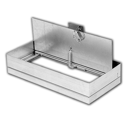
Equipped with fusible link at no extra charge.
Ceiling radiation damper installation instructions.
The damper surface mounted diffuser shall be installed as shown on the installation sheet.
Ceiling radiation damper and grille neck may be connected.
Models crd 1 crd 1lp crd 2 and crd 60 may be installed as shown in figure 7 model crd 1 crd 1lp illustrated.
The cfd2 is a ul555c classified ceiling fire damper.
These installation instructions apply to ceiling radiation dampers of the round rectangular single and butterfly blade types installed in a ul rated floor ceiling or roof ceiling assembly.
Each type of damper support system is described with damper being mounted in conjunction with various air devices.
The damper shall be installed as shown on the installation sheet.
For ceiling radiation dampers however since ceiling radiation dampers serve a somewhat different purpose than the other damper types there is often confusion about where a ceiling radiation damper should be used.
Ceiling radiation damper application.
These installation instructions apply to ceiling radiation dampers mounted in 3 hour rated ceiling with supports from 1 a ceiling grid system 2 ductwork above or 3 structure above.
Ul rated fire smoke and ceiling radiation dampers.
To better understand ceiling radiation dampers.
A minimum of two con nec tions per side.
A steel angle should be attached to the bottom of the ceiling radiation damper and span the gap from the ceiling radiation damper to the bottom of the ceiling membrane see detail d figure 7.
Up to 3 hour ceiling radiation damper installation instructions ceiling radiation dampers ii cfd15 february 2013 a.
The nominal size of the ceiling radiation damper.
These instructions address the different applications of installing the dampers in a ceiling with supports from 1.
Connection of ceiling radiation damper grille and steel duct drop may be satisfied in two ways.
Let s examine the protection provided by each type of damper.
For example a 12 x 12 305 x 305 ceiling radiation damper could have a maximum ceiling membrane opening of 13 x 13 330 x 330.

